
AISTech 2025, Nashville, Tennessee (EUA)
Optimization of Steel Plate Storage Yard Crane Scheduling
Heurística que sequencia os movimentos de ponte rolante em pátios de chapas, reduzindo de cinco para um os movimentos necessários em cerca de 50% dos carregamentos.
Aplicação prática na indústria (Movimentação de pontes rolantes em pátios de chapas)
Quando o estoque está mal posicionado, cada carregamento exige remanejar chapas, e a ponte rolante vira gargalo da expedição. O artigo decide a próxima movimentação da ponte pensando na carga inteira.
Do conceito matemático ao ganho de negócio
- Heurística de minimização de movimentos
- Para cada carga, indica a sequência de movimentos da ponte com o menor número total de remanejamentos.
- Restrições de equipamento e empilhamento
- Limites físicos das pontes, mesas de rolos e regras de empilhamento entram no cálculo, e não só a posição das chapas.
- Ordem de carregamento
- O carregamento segue a ordem que os veículos precisam, sem desorganizar o pátio para as próximas cargas.
Resultado: Em um caso real, metade dos carregamentos passou de cinco movimentos para um, e o pior caso caiu de 15 para 6 movimentos.
Ver o case: Movimentação de pátioAplicações em Siderurgia
Resumo executivo da Enacom, em português, a partir do artigo e dos projetos relacionados.
Resumo
Um dos grandes desafios da produção de chapas de aço é armazenar o material de forma eficiente, para agilizar o carregamento dos veículos e manter a organização do pátio. Além das limitações físicas dos equipamentos responsáveis pelas movimentações dentro dos pátios e entre eles, esse tipo de problema envolve uma série de restrições que aumentam sua complexidade. Este estudo propõe uma solução de otimização para o problema de movimentação de pontes rolantes nos pátios de armazenagem de uma siderúrgica. Para isso, será apresentada uma abordagem heurística que determina as próximas movimentações da ponte de forma a minimizar o número total de movimentos necessários para concluir o carregamento das chapas. A solução proposta mostrou-se mais eficiente que as operações manuais realizadas pelos operadores de ponte em um caso real. Os resultados mostram que a otimização conseguiu reduzir de cinco para um o número de movimentos necessários para realizar os carregamentos em cerca de 50% dos casos, além de reduzir o número máximo de movimentos de 15 para 6.
Resumo traduzido do original, publicado em inglês.
Palavras-chave
algorithmcraneoptimizationloading orderconstraintroller tablecrane movementscheduling
Artigo completo
Texto completo do artigo, em inglês, conforme publicado na revista Iron & Steel Technology, junho de 2026 (vol. 23, n. 6, p. 68–73). © Association for Iron & Steel Technology.
1. Introduction
The manufacturing process of steel products involves several stages, from the arrival of raw materials at the plant to the shipment of the product to customers. Planning these stages is a highly complex task due to the vast amount of information that must be considered during decision-making. Given this complexity and aiming to ensure productivity while minimizing undesirable scenarios, it is essential to adopt methods that optimize each stage of production.1 A viable and effective alternative is the use of computer-assisted optimization combined with digital twin technology, which has been widely adopted by the industry.2,3 These technologies have supported all stages of steel production, offering benefits such as increased productivity and greater predictability throughout the production chain.4
Among the stages of the steel plate production chain, storage and logistics play a crucial role in maintaining the entire production flow.5,6 If storage yards reach their maximum capacity, earlier production stages such as the steel mill and rolling mill be affected, potentially even requiring production to be halted due to a lack of storage space. In addition to impacting the production department, steel plate storage can also affect other areas, such as logistics, which is responsible for shipping the plates to customers. When storage is not carried out correctly, vehicle loading can become a complicated task, as the plates needed for shipping may be scattered across multiple stacks or buried under other plates, leading to shipment delays.
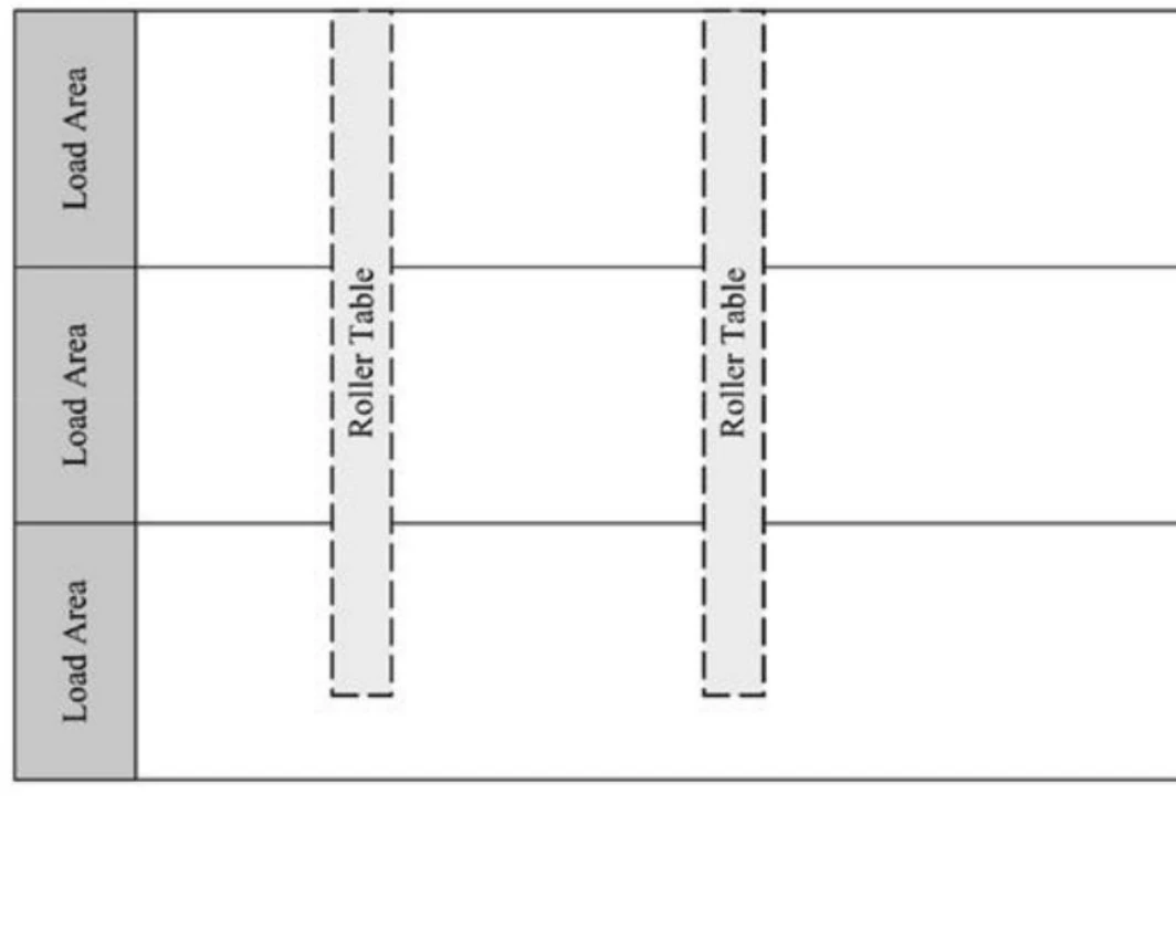
Material storage takes place in yards, where each yard consists of an area subdivided into stacks, each stack containing a set of plates. In this study, plate storage is carried out in three different yards, as shown in Fig. 1. These yards are connected by two roller tables, which, in addition to receiving plates from the rolling mill, are also responsible for sending plates to the ultrasound inspection and transferring them between yards. Plate movement within the same yard is carried out using cranes. This equipment consists of a main beam that moves along rails fixed to lateral structures, allowing load movement along a horizontal axis. In this case, there are two cranes in Yard 1 and Yard 2 and one in Yard 3.
The right and left edges of each yard are designated for vehicle loading. The position where each vehicle will be placed for loading depends on the location of the plates assigned to that vehicle, both in terms of the yard and their position within it. For example, if a set of plates to be loaded is located on the left side of Yard 2, then the vehicle should be positioned in the leftmost loading area of Yard 2.
Based on the yard structure described above, plates follow specific flow paths within the yards depending on their characteristics. After being rolled, plates arrive at the yard via a roller table. A crane must then pick up this material and place it in a designated stack within the yard. A plate in the yard may be moved to another stack, sent to the roller table for ultrasound inspection or transferred to another yard, or loaded onto a vehicle for customer delivery. The primary goal of these movements is to keep the yard organized, facilitating both the shipment of plates to customers and the reception of newly rolled plates, while also minimizing the number of movements required for loading operations.
To carry out movements within a yard, cranes are crucial equipment and often represent a bottleneck in the storage and dispatch process. Therefore, optimizing the number of movements performed by these cranes is essential to improving yard operations.6,7 These crane movements can be categorized into four types of tasks: receiving plates from the rolling mill, sending plates to ultrasound inspection, loading plates onto vehicles and organizing the yard. In this study, these movements are treated independently; for example, loading movements do not influence the organization or reception of plates from the rolling mill. The choice of which type of movement will be performed next is at the discretion of the overhead crane operator.
The objective of this study is to present an algorithm capable of determining the next movements of the cranes to achieve loading operations with the fewest possible movements while also organizing the yards to facilitate future shipments and keep plates grouped together. To achieve this, a heuristic approach was proposed to identify the next necessary movements for loading operations and yard organization. For each possible type of movement (loading, organization, receiving plates from the rolling mill and sending plates to ultrasound inspection), the algorithm lists the next possible movements that the crane can make. The best movement is then selected to minimize the total number of movements required for plate loading while maintaining yard organization.
2. Discussion
2.1 Problem Definition
This section presents a low-level definition of the crane scheduling problem in steel plate storage yards, which will be solved by the algorithm. This definition outlines the problem’s inputs, the algorithm’s output, the objective function and the constraints.
Input and Output
The main input parameters of the problem are:
- List of plates.
- List of yards.
- List of stacks.
- List of roller tables.
- List of cranes.
- List of loading orders (a loading order specifies which plates need to be loaded onto a specific vehicle).
The algorithm’s output consists of the movements performed by each crane, grouped by movement type:
- Loading movements.
- Organization movements.
- Movements for receiving plates from the rolling mill.
- Movements for sending plates to ultrasound inspection.
Each movement group is represented by a list that stores the movements the crane must perform. These movements are ordered according to the sequence in which they should be executed. Each movement is specified by the yard with starting and ending coordinates and the plates to be moved. For loading movements, additional information about the corresponding loading order and the vehicle receiving the plates is provided. Organization movements also include an indicator of their purpose, such as whether they are related to preparing for a future shipment or grouping plates together.
Objective Function
The objective is to minimize the number of movements required to load all the plates from the loading orders. Additionally, when performing other types of movements, the goal is also to reduce the number of future loading movements.
Hard Constraints
In this subsection, the main hard constraints of the problem will be presented. Hard constraints must be strictly followed in the solution. These constraints are mainly related to the operational rules of cranes, storage yards, stacks and equipment availability.
Yard constraints
- Each yard has a designated usable area that indicates where stacks can be positioned.
- Stacks within a yard must comply with a maximum height limit.
- Some areas within the yards have restrictions on the dimensions of the plates that can be stored in those locations.
Crane constraints
- Each crane can move only a limited number of plates at a time, depending on the dimensions and weight of the plates.
- Cranes can reach only specific areas within the yard.
- Some yard areas can be accessed by multiple cranes, but a minimum safety distance must be maintained between them.
Stack constraints
- Only the topmost plates in a stack can be moved at any given time.
- Plates must always be placed on the top of a stack.
- The variation in plate length and width within a stack must be restricted.
- The stacking of plates on railcars and trucks must follow a semipyramidal structure, meaning that the plate on top must not exceed a certain size difference in length or width compared to the plate below.
Equipment availability constraints
- A crane that is unavailable cannot be used.
- A roller table that is unavailable cannot be accessed by a crane.
- A yard area under maintenance cannot be accessed by a crane.
- Plates must not be sent to ultrasound inspection if the ultrasound machine is unavailable.
Soft Constraints
In this subsection, the main soft constraints of the problem will be presented. Soft constraints are not mandatory but are desirable for achieving a solution that better aligns with customer expectations. These constraints are related to mainly the grouping of plates within stacks. Ideally, plates with similar characteristics should be placed in the same stacks to maintain yard organization and facilitate preparation and loading movements. The soft constraints for this problem are:
- Keeping plates with similar characteristics grouped within the same stack.
- Grouping plates from the same loading order into the same stack.
- Avoid stacking new plates onto stacks that are already prepared for shipment.
- Plates with older sales dates should be placed at the top of the stack.
- Plates coming from the rolling mill should be assigned to stacks that will facilitate future shipments.
2.2 Main Algorithm
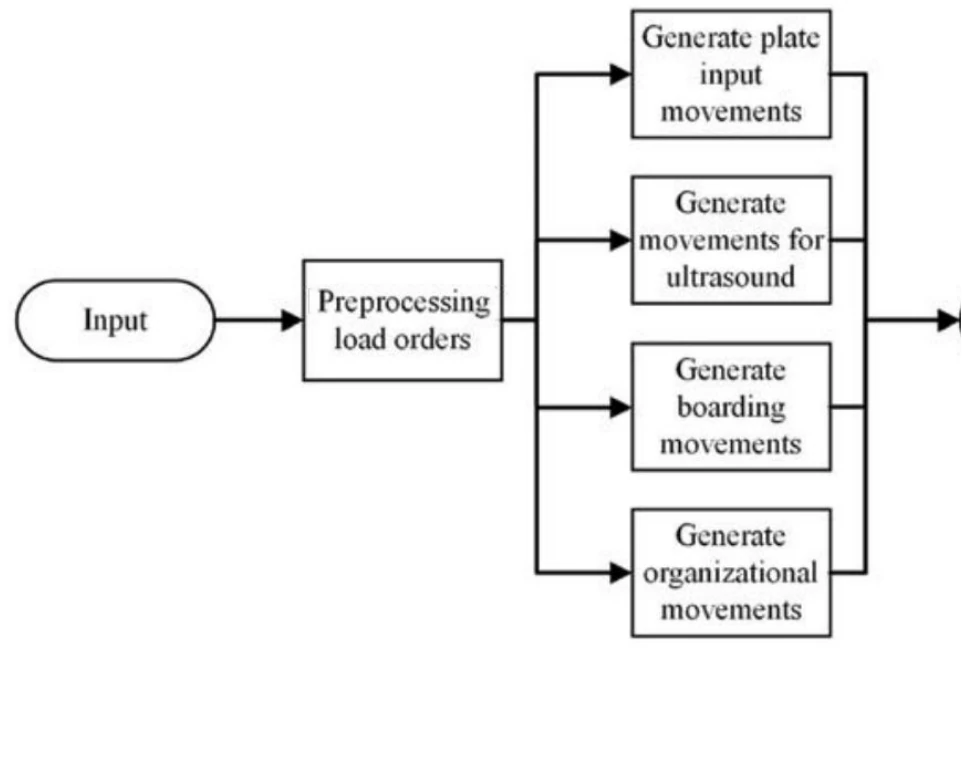
The algorithm designed to solve the problem consists of four main components, in addition to a preprocessing stage for loading orders. A flowchart of this algorithm is presented in Fig. 2. The components are divided into generating movements to assign plates coming from the rolling mill, sending material for ultrasound inspection, loading vehicles and organizing the storage yards. After executing these steps, an object is generated containing the movements for each stage. It is important to note that each component generates a set of movements independently, meaning that the initial state of the yard serves as the input for each step.
The most critical stages of the process are loading movements and organizational movements, as these tend to require the most crane operations. The following paragraphs provide a more detailed explanation of each step.
Preprocessing of Loading Orders
Before starting the other stages of the algorithm, it is necessary to preprocess the loading orders. Initially, these loading orders are sorted according to the scheduled date for their departure. If the vehicle is already in the yard waiting for loading, this loading order will be processed in the movement generation stage for loading. If the vehicle is not yet in the yard, the loading order is listed to be prepared for boarding during the yard organization movements.
After being sorted among themselves, the plates belonging to that loading order are also sorted with the aim of reducing the number of movements needed for boarding. To carry out this sorting, the order in which the plates appear in the source stacks is considered. Stacking restrictions for the plates in the destination stacks or on the vehicle must also be considered to perform the sorting of these plates.
Generate Plates Entry Movements
This stage is responsible for directing the plates coming from the rolling process to a compatible stack. When rolled, the plates are placed on the roller table and directed to one of the yards. Upon reaching the destination yard, this plate must be taken to a stack. The chosen stack should be the one that has the greatest compatibility with the plate that has just been rolled and does not break any height or dimensional restrictions.
Generate Movements for Ultrasound
Some plates need to be inspected via ultrasound before being dispatched to the customer. These plates are usually grouped in piles in the yard. At some point they must be taken by crane to the roller table, which in turn will transport the plate to the ultrasound equipment. Upon leaving the equipment, the plates are again collected by the cranes and directed to compatible stacks. Just like in the stage of addressing the rolling plates, choosing the destination stack for the plates coming out of the ultrasound is important to maintain the organization of the yard; therefore, the stack with the highest compatibility should be selected.
Generate Boarding Movements
Loading movements can be more complex than those previously presented due to the need for additional movements to complete the loading process. Additionally, the order and destination of these movements are crucial to maintaining organization and ensuring that the loading is carried out correctly.
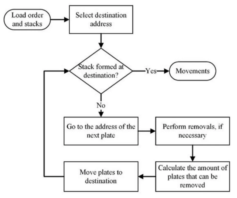
When the plates for a loading order are already prepared in a stack ready to be loaded, the loading activity becomes simple. In this case, the crane must be positioned above the source stack, lift as many plates as possible, and transport them to the vehicle, repeating these movements if necessary. However, if the plates are scattered throughout the yard or buried under other plates, the loading task becomes more complex. In this case, the crane will need to access multiple stacks or remove several plates to reach the specific plate that needs to be loaded. Fig. 3 shows the flowchart for generating movements.
The first step of the algorithm to generate loading movements is to identify the address where the plates will be placed. In this case, it is the address where the vehicle is positioned in the yard. Next, the stack where the first plates of the loading order are located must be identified. After identifying the source stack, it is necessary to analyze whether the plates that will be loaded are buried by other plates; that is, whether the plate candidate for shipment has any plates on top of it in the stack. In this case, the plates that are preventing access to the plate from being loaded must be removed to another stack until the plates for shipment are on top. Given that the plates are already on top, the number of plates that can be moved by the crane is then calculated, considering the capacity restrictions of the crane that will be used for the movement. The plates can then be moved to their destination. This process is repeated until all the plates of the loading order are at the destination address.
Generate Organization Movements
Organization movements can be categorized into three types: preparation for loading, undoing removal and grouping plates. These movements are distinguished in the output by means of a parameter that identifies the type of organization movement for each movement in the list.
Preparation for loading movements are generated when there is a loading order, but the vehicle has not yet been positioned in the yard. The plates for this order can be arranged to facilitate loading once the vehicle is in place. The process for this organization follows the flowchart in Fig. 3, but instead of the destination being the vehicle, it will be a stack in the yard. This way, the plates from the loading order are grouped into a single stack while maintaining the order in which they will be loaded onto the vehicle.
Removal return movements occur when a plate needs to be loaded but is buried under other plates in a stack. In this case, the top plates are moved to other stacks until the plate to be loaded is at the top. After loading the plate, the plates that were previously removed to uncover it must be returned to their original stack.
Plate grouping movements are aimed at organizing plates with similar characteristics to maintain order in the yard. If a plate is in a stack that is not compatible and there is space in a compatible stack, the plate should be moved to a more suitable stack.
Select the Best Move
In certain types of movements, especially organizational ones, there are multiple possibilities for relocating one or more plates between yard stacks. In these cases, all valid movement options are listed, and one is selected based on a set of criteria used to determine the optimal choice. The criteria for selecting the movement include:
- Grouping plates by sales order.
- Grouping plates ready for boarding.
- Grouping plates by customer.
- Grouping plates by itinerary.
- Emptying stacks.
- Minimizing the number of removals.
- Reducing the crane’s movement distance.
Once the movement is selected, the crane is directed to the source stack, where it collects the designated plates and then places them in the destination stack.
3. Results
This section presents the results obtained from executing the previously discussed algorithm in a real-world scenario involving a set of steel facility plate yards. As input, the algorithm receives a data set representing a real instance of the initial state of the yard and the loading orders information. After generating optimized movements using the algorithm, the results are compared to the manually planned movements by crane operators.
Figs. 4 and 5 illustrate the results obtained from the manual planning by the operators and the optimized planning, respectively. The horizontal axis represents the number of movements required to complete the loadings, ranging from 1 to 15. The orange line indicates the cumulative percentage of loadings completed with the given number of movements, while the green line shows the specific percentage of loadings performed with indicated number of movements.
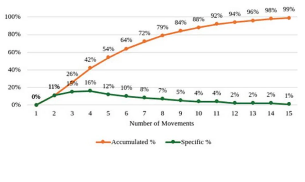
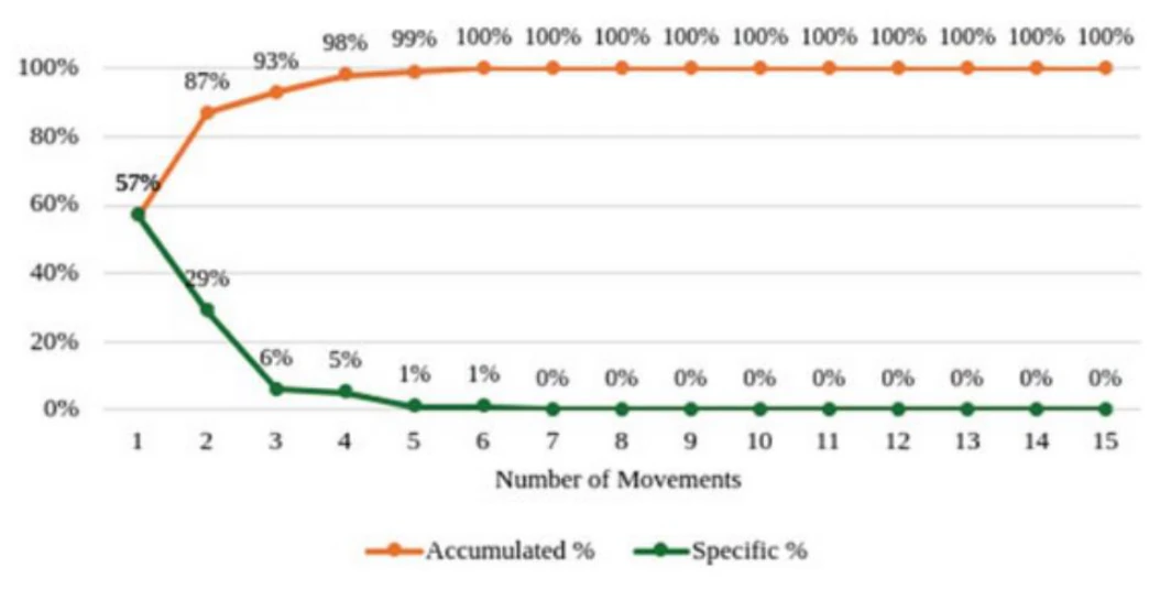
A comparison of the two graphs reveals a significant improvement in the number of movements in the optimized planning. In the manual planning, 54% of the loadings were completed using a maximum of five crane movements, whereas the optimized approach achieved 57% of the loadings with just a single movement. Additionally, in examining the maximum number of movements required to complete a single loading, manual planning required up to 15 movements, while the optimized planning reduced this to just six.
The implemented algorithm has proven effective in optimizing crane movements within the plate yards analyzed in this study. This improvement is due to the algorithm’s ability to process the yard’s information, enabling it to determine the most effective movement alternatives. In contrast, during manual planning, the crane operator lacks the capacity to analyze a massive amount of information that could be crucial for identifying the best movements. Furthermore, whether performing loading operations or organizing the yard, the algorithm can evaluate the most efficient movements to facilitate the loading of future shipments.
4. Conclusions
Maintaining organization in the storage of steel plates is a crucial factor in the production chain of a steel facility. The resources available to move these materials while keeping the yard organized are limited, making it necessary to optimize the entire movement process from receiving the plates to organizing and finally loading them. This study presented an algorithm capable of optimizing crane movements to minimize the number of movements required to complete the loading of a vehicle. Additionally, the algorithm performs yard organization movements to create homogeneous stacks, meaning plates with similar characteristics are grouped together, which also facilitates the loading of future orders.
The results obtained by executing the proposed algorithm on a real data set demonstrate that the solution outperforms manual execution by crane operators. This improvement is primarily due to the operator’s limited view of the yard, which causes many possible solutions to go unnoticed. In contrast, the algorithm can analyze multiple movement combinations, allowing it to identify the most optimal solution for the yard’s current state while also executing movements that streamline future loadings.
Future work includes applying this algorithm to yards with different characteristics from those presented in this study and exploring other algorithms that may be suitable for this type of problem. Additionally, integration with existing systems in the same plant could be explored, such as the digital twin of the plate rolling stage, which could enhance the accuracy of movement planning for newly rolled plates being placed in the yard. Another integration possibility is with the plate loading planning module, allowing the algorithm to process a larger set of future loading orders, further optimizing the loading process.
Acknowledgments
This work was the result of an Enacom project in association with Gerdau. The authors are thankful for the support of FAPEMIG and CNPQ.
References
- J. Schulz, “Applying Mathematical Optimization in Practice,” SN Operations Research Forum, Vol. 2, No. 3, January 2021, pp. 1–12, https://doi.org/10.1007/s43069-020-00046-9.
- Z. Xu, Z. Zheng and X. Gao, “Operation Optimization of the Steel Manufacturing Process: A Brief Review,” Int J Miner Metall Mater, Vol. 28, No. 8, February 2021, pp. 1274–1287, https://doi.org/10.1007/s12613-021-2273-7.
- M. Javaid, A. Haleem and R. Suman, “Digital Twin Applications Toward Industry 4.0: A Review,” Cognitive Robotics, Vol. 3, April 2023, pp. 71– 92, https://doi.org/10.1016/j.cogr.2023.04.003.
- Y. Zhang, M. Sukhram, I. Cameron and A. Rozo, “Industrial Perspective of Digital Twin Development and Applications for Iron and Steel Processes,” AISTech 2020 Conference Proceedings, 2020.
- Z. Zhang, P. Wang and W. Wang, “Optimization and Operation Scheduling for a Steel Plate Yard Based on Greedy Algorithm,” Journal of Networks, Vol. 8, July 2021, https://doi.org/10.4304/jnw.8.7.1654-1659.
- X. Wang, M. Zhou, Q. Zhao, S. Liu, X. Guo and L. Qi, “A Branch and Price Algorithm for Crane Assignment and Scheduling in Slab Yard,” IEEE Transactions on Automation Science and Engineering, Vol. 18, No. 3, July 2021, pp. 1122–1133, https://10.1109/TASE.2020.2996227.
- A. Dohn and J. Clausen, “Optimising the Slab Yard Planning and Crane Scheduling Problem Using a Two-Stage Heuristic,” International Journal of Production Research, Vol. 48, No. 15, July 2009, pp. 4585–4608, https://10.1080/00207540902 998331.
Quer conversar sobre o que leu?
Conte o desafio da sua operação e nossa equipe avalia com você por onde começar.